Archive for July, 2013


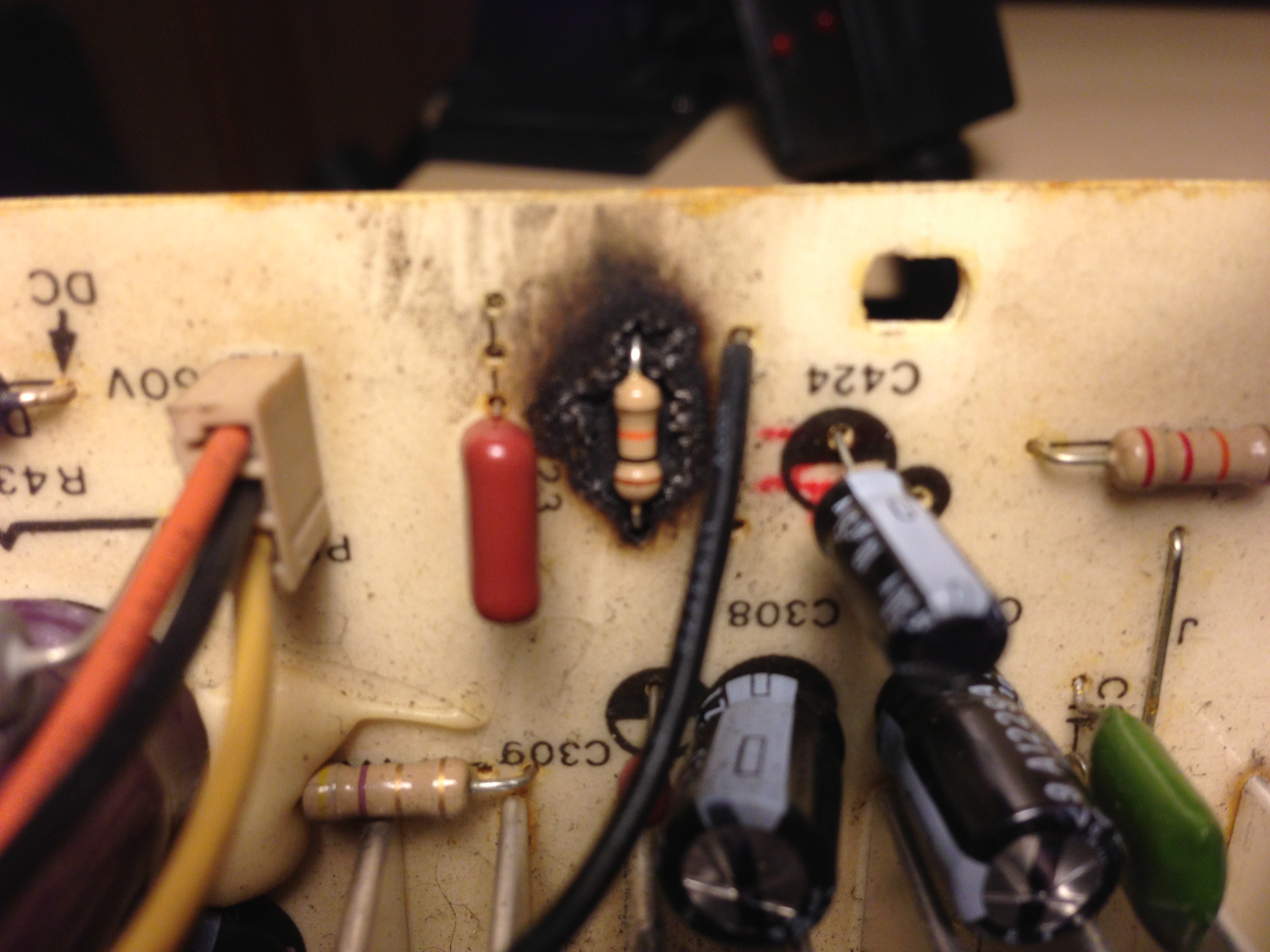
It’s hard to tell what went first…  Was it the flyback?  Maybe it’s the mylar with the guts oozing out the side.  The weak green gun on the crappy Zenith A68AGD01X tube?  Perhaps it was a perfect storm but my sneaky suspicion is still that something went first before the rest.  The frusteration came however when I replaced the flyback, all the burnt components and all of the caps and still got no signs of life.

bad electrolytic


bad mylar

scorched resistor


That signaled the time to bring in the rejuv.  I haven’t used a rejuv in years so this was pretty exciting.  One of my friends just picked up a Sencore CR70 off of eBay.  It’s a really sweet box.  Way nicer than the one I used at All Repair back in the day.  This one only has 5 sockets.  You set the wiring diagram but using a series of switches on the unit itself.

Anyhow, we fire up the rejuv and found the green have pretty lousy emissions.  Worst yet, the cutoff didn’t even register on the scale until we cranked the negative bias from the recommended 68v down to somewhere in the 35v range.  We hit it with the auto rejuv 3 times and then with the manual cycle.  This brought the emissions back to the level of the other guns but not the cutoff.  There was a little bit of improvement but it’s a clear sign that this tube will need to be replaced sooner than later.

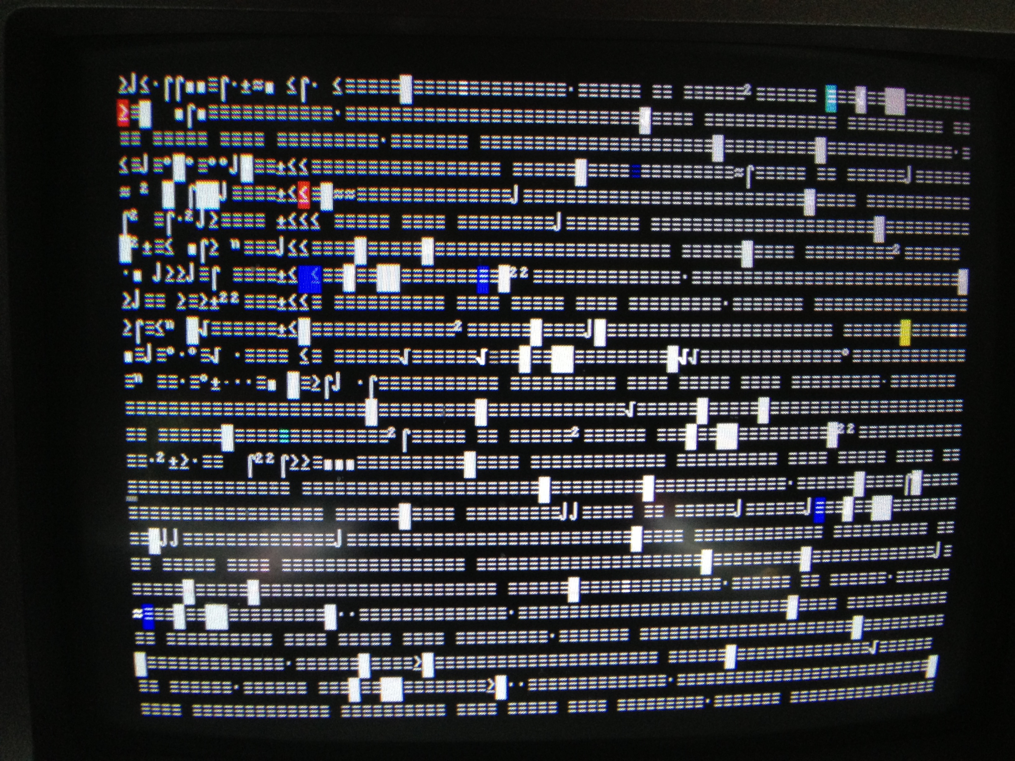
After rejuving however it still didn’t work.  We had heater and high voltage though so we were a bit perplexed.  We ended up checking the G2 voltage live in circuit.  The most we could squeeze out of it was 190v or so.  This was way too low given that a similar chassis with the identical tube a few games downw was putting out 290v to get a reasonable picture.   We had the Neotec NT-27E service manual so we gave the schematic a once over.   It APPEARED that our fault may have been in the brand new flyback but my friend didn’t want to give up so easily.  he decided to check every pin of the CRT to ground.

scorched socket

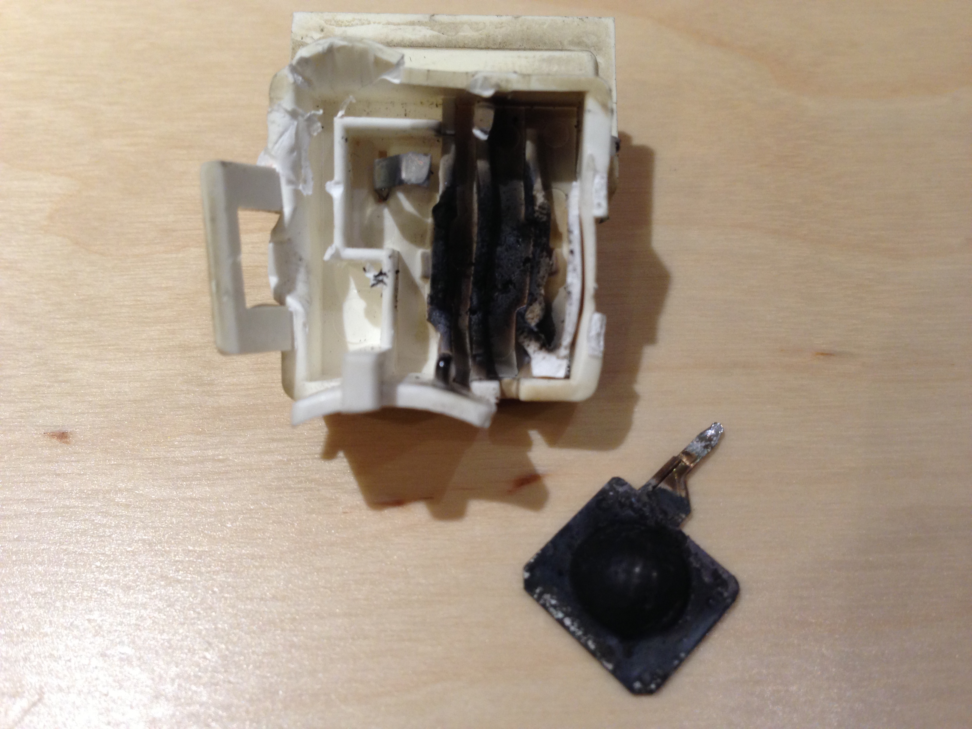
Low and behold, G3(focus) was reading less than 1M of resistance to ground.  Not particularly good.  A closer look at the socket revealed that it had gotten really hot.  We picked at it until it opened up and ended up with a handful of carbon residue.  It turns out there is a spark gap inside of this socket.  It had started arcing which produced some carbon.  This led to more arcing until the focus had shorted enough to ground where it was also dragging down the G2 voltage substantially.

For the moment, we yanked the spark gap and soldered the focus wire directly to the focus pin.  Needless to say it fired right up.

Not sure how long this would have taken me to discover myself but it was a darned good find on my friend’s part.  Very impressive.

Fixing the AT&T 6300/Olivetti M24

I was at the computer recycler a couple of years ago and this machine caught my eye.  It was a very different looking machine compared to others of it’s era.  The case has a sidecar for the hard drive unit which makes it look even more odd.  When I bought it, the monitor and keyboard cables had been cut in two.  Instead of reaching around with a screwdriver to properly remove the cords, someone just decided to slice the cables.

I fixed that at least a year ago.  I popped open the monitor and meticulously sorted out all of the wires needed.  You might think that would be fairly trivial but this monitor uses a DB25 connector.  I didn’t know it was actually a color CGA (sort of) monitor until I popped it open to do the sorting.  After a couple hours of sorting, I finally got it all wired up.  I plugged it in and saw this:

garbled olivetti screen

At that point it became obvious why the computer was discarded.  I got busy and stuck the machine aside.  Recently, in a fit of cleaning, I stumbled on the machine again (literally).  I figured it was time to do something with this box or toss it.

I fired it up to the same old familiar screen.  Next, I pulled ALL of the cards.  I wanted to make sure those weren’t somehow acting poorly.  This machine is VERY unique.  The video card is also the backplane.  The motherboard lives on the bottom of the case and is connected to the expansion slots via the video card.  When I get the machine fully running, I’ll post more pictures that will better explain this.

IMG_0802

Once I had room to maneuver, I hooked up my logic probe and logic pulser and actually managed to locate a schematic for this beast.  I started out just probing around randomly until I find some interesting signals.  Occasionally I would hit a chip with the pulser.  Usually the effect was just some noise in the video signal but then I started getting closer to the right section.  I found a chip to probe where on of the pins would pulse every time the flashing line on the screen changed.  AHA!  Must be close now.

I looked some more at the schematic and found the character ROM where the default font is stored.  I probed around on it and decided that it must be bad since it’s the only thing I can’t replace… so I thought.  I took a look through my junk box and found the original CGA video card that came with my PCXT.  Low and behold it had the exact same EPROM on it.  I figured that was random luck though and there would be no way it would work even if it was the same chip.

I decided to swap it and by some form of magic, it did in fact work.  The problem still remained exactly the same though.  I decided this was good though and moved on to other areas.  I decided to eavesdrop on the four TMS4416-15NL DRAM chips.  I figured that the signals in and out of them should all be similar so I compared the signals.  I found that one of the chips had a couple of dead data out lines.  Since all of the address lines appeared to be doing what I would expect, I determined that this one chip must be the problem.  I also decided to hit a couple of the lines with my pulser.

IMG_0801

This reaction proved that I was on the right track.  Once again, I went searching on the IBM CGA adapter and found an exact match for the ram chip I needed.  Thankfully, the ram on the IBM board is socketed.  Unfortunately this is not the case with the Olivetti board.  I had one socket that fit in my parts box though so I popped that onto the Olivetti board and popped the chip into it.  After reassembling enough of the machine to test the board, I was eventually rewarded with this:

Olivetti Working 1.43 BIOS screen

This is probably not the end of the problems with this machine.  Far from it in fact but it’s an interesting machine in good condition so it’s well worth the effort and the digital trouble shooting skills I’ve gained from this experience are well worth the money I paid for the machine in the first place.

Powered by WordPress. Theme: Motion by 85ideas.