
During the holiday season here I had some time to tackle some of the projects that have been on my todo list for ages. One of these projects was improving the video output from my Aquarius. Last time I hooked it up, the picture was pretty horrible. It may have been a flaky RF switch box but an RF modulated video signal isn’t really ideal in the first place. Searching around, I found some schematics for the Aquarius so I thought this project would be a piece of cake.
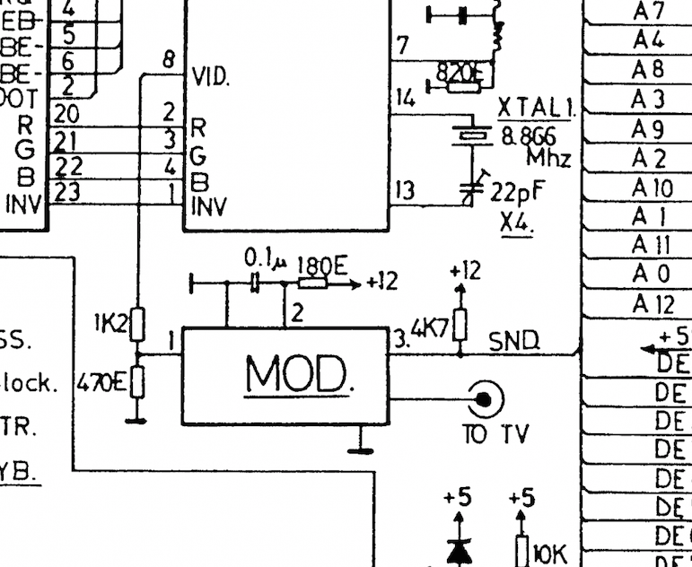
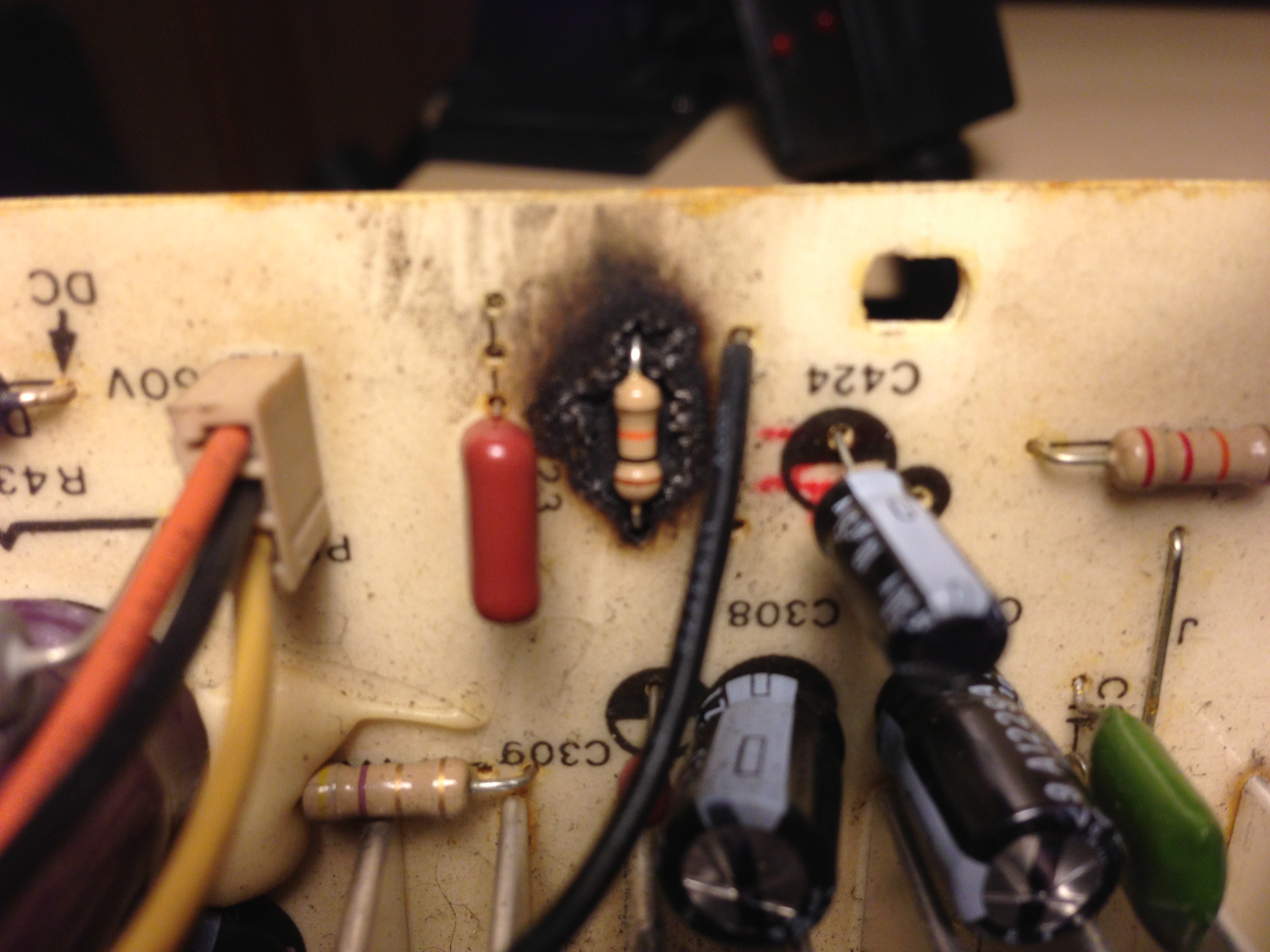
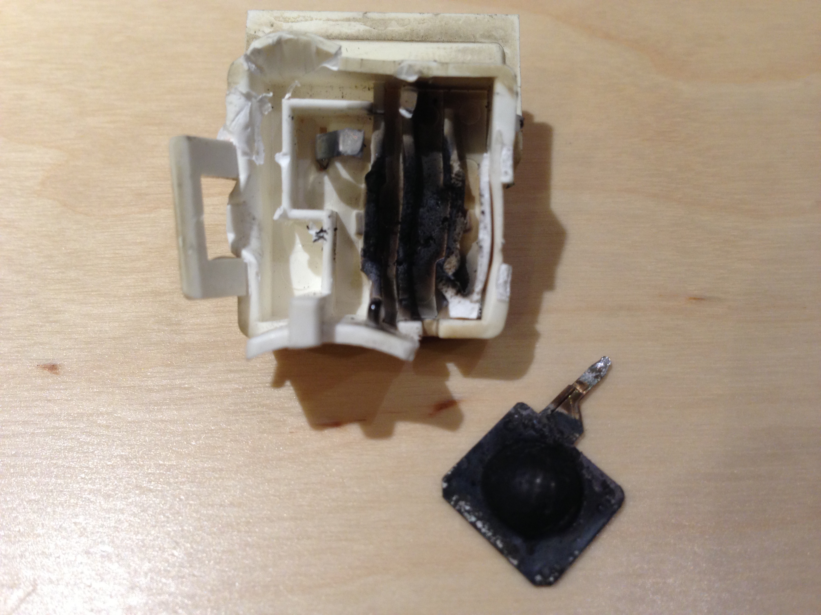
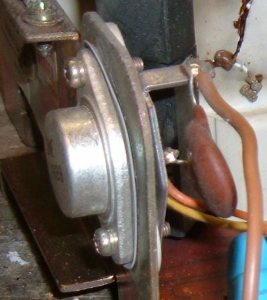
Here is the offending RF modulator
It appeared to be a simple matter of removing the RF modulator from the board and then grabbing pin 1 and feeding it to a RCA jack and feeding pin 3 to another for sound. When I did that though, I got video like this:
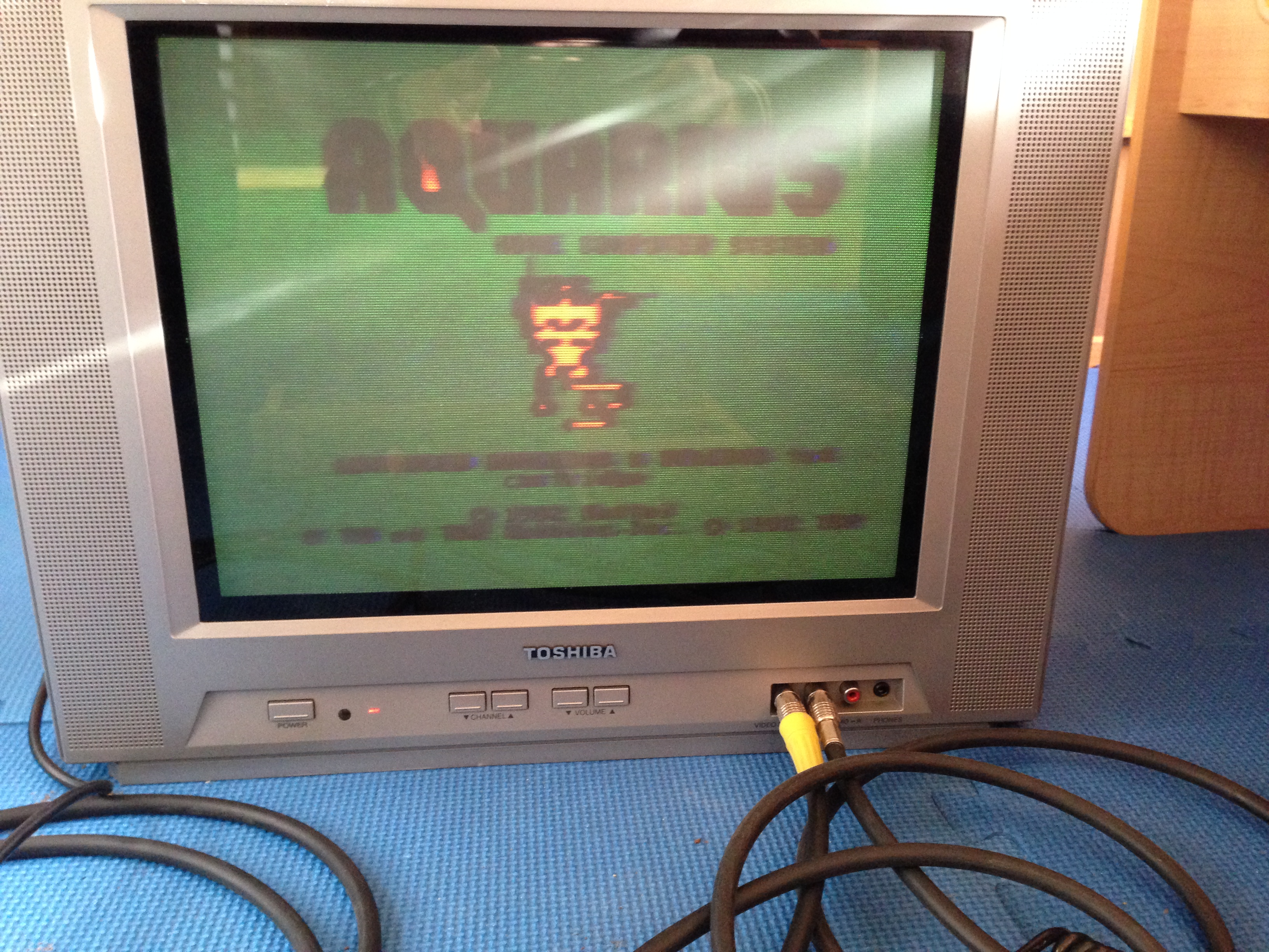
Wrong colors, smearing, sync loss, illegible text. Yuck!
It was at this point that I realized the project might not be as easy as I first thought. I decided that the problems was a weak signal so I set out to try to amplify it.
I was a little puzzled as to why such a weak signal worked fine for the RF modulator but not for the TV. When I looked at the signal on a scope, it looked fine:

This is the unloaded signal straight out of the TEA1002 chip with the two resistors in place.
But then when I put a resistor across the signal to load it down, it squashed down to nearly nothing. Apparently the RF modulator doesn’t have much of a load at all since it has no 75 ohm cable termination to deal with.
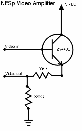
I unsuccessfully tried a couple of single transistor emitter-follower circuits such as this NES Video Booster circuit that I found. While it improved the signal, it didn’t entirely fix the problem. My friend suggested a purpose built video buffer chip such as the MAX4090. Oddly, he had a roll of 200 of them laying around that he never found a use for. I hooked it up on my breadboard to check it out:
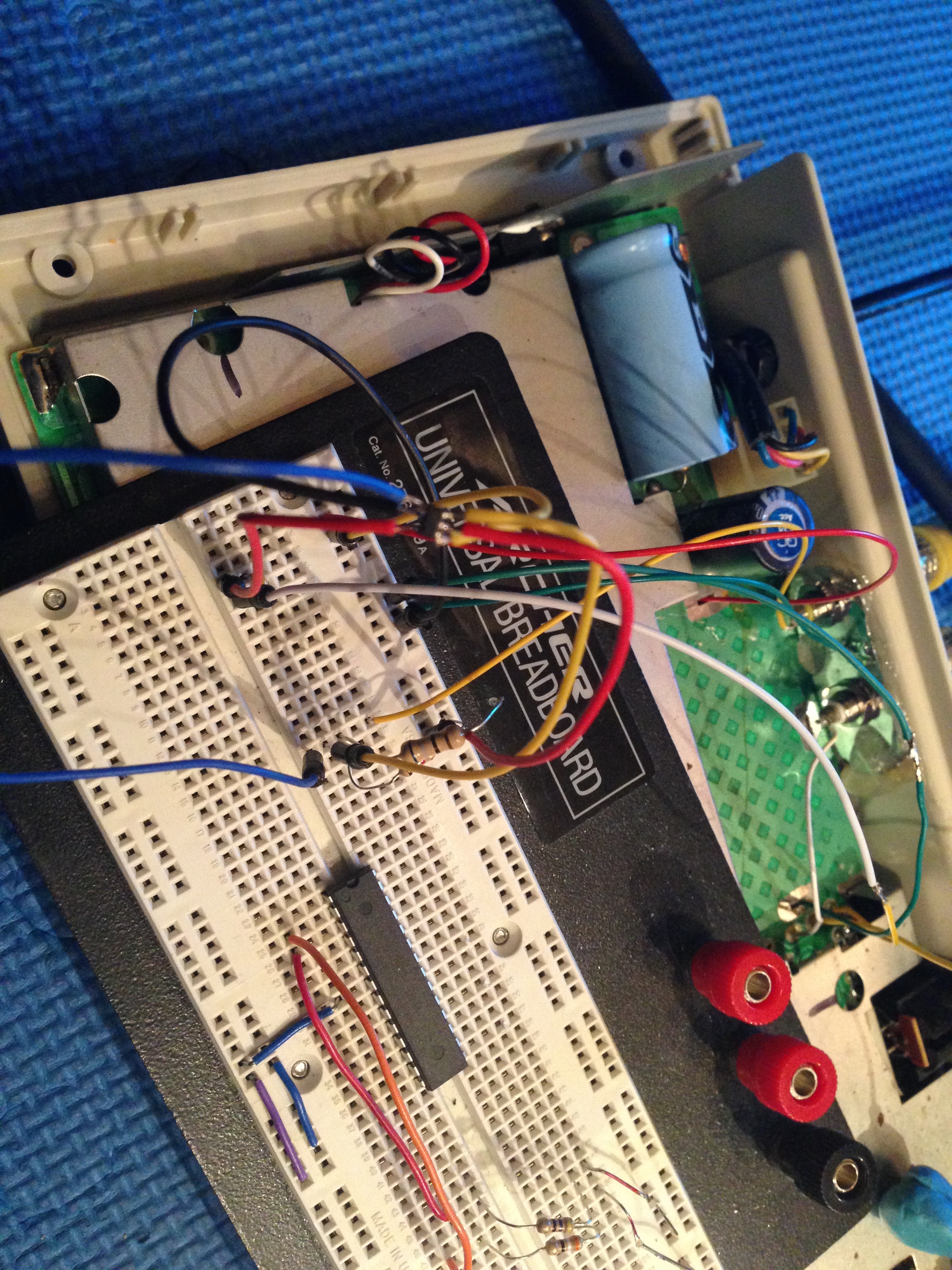
Breadboarding an SOT23-6 packaged chip was a small challenge but certainly not impossible.

That’s more like it! (Ignore the moire pattern from my cell phone cam)
Success! That worked pretty well. I started with the reference circuit found in the MAX4090 datasheet but found that it worked best with only the one cap installed on the output. I omitted all of the resistors from the circuit and the decoupling cap on the vcc. Just in case though, I designed my PCB off of the reference schematic:
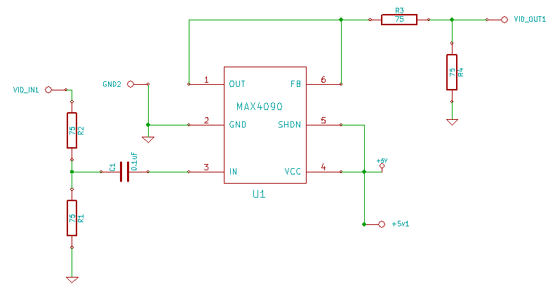
MAX4090 Breakout Board Schematic
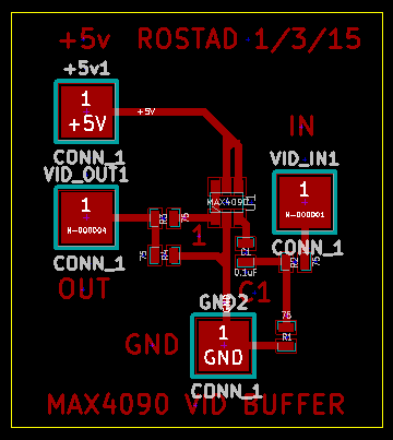
Here’s my Kicad layout for the breakout board.

Here’s the breakout board installed in the Aquarius. Fits where the RF modulator was.

This is how it should have looked from the factory the day it was shipped!
In case you are wondering about the red +5v line, I got that from the bottom of the board. The 5v regulator line is very clearly marked on the solder side over near where the three wires from the regulator go under the metal shield. I just followed it as close to the former location of the RF modulator and grabbed it there.


