Tag Archive: arcade


MA-309The MA-309 is the same as the MA-216 without the SC-01a speech chip and support circuitry installed. It was used in the System80 pinball machines Super Orbit, Royal Flush Deluxe, Amazon Hunt, Haunted House, Spirit, Krull, Goin’Nuts and video game Mad Planets. It will also work with ROMs from Mars, Volcano, Black Hole, Devil’s Dare, Rocky, Striker, Q*Bert’s Quest, Caveman and video games Reactor, Qbert, Krull, Three Stooges  although the speech feature from this game will obviously not work. If someone implements the SC-01a in HDL then adding the support logic is trivial.

This code works as-is on the cheap Alterra Cyclone II dev boards available on eBay for $20 or so.  Hook up a PS/2 keyboard to it and you can trigger the sounds with it.  Disable/remove the PS/2 code and this should plug straight in to one of the real machines listed above.

https://github.com/FPGA-Code/Gottlieb-MA-309


This monitor has been on my desk for months because I’ve been avoiding it but I’ve decided that it’s taking up too much space so I’ve decided to start digging into it again.  I’m going to document my repairs here in hopes that it will help someone else out to see my troubleshooting process.

The symptom of the issue is no picture.

The problems are several.  The monitor is switchable between standard and medium resolution hence the “DS” in the model name which stands for dual sync.  When I attempt to run it at 15k, things seems somewhat stable.  There is no picture but when I test B+, it will sit there right around 130v which seems pretty reasonable.  Testing with the high voltage probe I get about 130v on the anode which tells me something in the flyback/HOT area is not working correctly but I don’t have a schematic so I’m flying blind on it.  When I hit the base on the oscilloscope, I get a reasonably nice looking square wave that seems to be at the correct frequency and looks happy.

Oscilliscope reading (base)

So that makes it appear that the driving waveform is ok.  When I hit the collector, I get this:

Oscilliscope reading (collector)

That does not look good.  Theoretically I should be getting voltage spikes that go well of the screen when the HOT grounds the flyback.  The scope is set for 50 volts per div and I’m barely covering two of them so something is clearly wrong here.

When I switch over to medium resolution (25k jumper) things get much worse.  The B+ pops on and starts at about 140v, then it keeps climbing and the monitor starts getting noisy to the point where I’m concerned and then I shut it down.

I’ve tested the flyback with a ring tester and it looks good but perhaps there is a different problem with the flyback that cannot be diagnosed with that tool.  I know for sure the HOT is good, I have several of them and they all test the same.  When I pull the HOT out of circuit, both the 15k and 25k mode act the same and give the same B+ voltage of roughly 130v.  The only difference is the waveform reading on the base of the HOT.

S.T.U.N. Runner Random Resets

IMG_0853

The opportunity finally presented itself for me to buy a full-sized arcade game.  I suppose I could have picked a smaller one but I kind of bought it on a whim.  The game?  S.T.U.N. Runner.  It’s a sit down “cockpit” style racer with no gas pedal.  It’s a game that I used to play all the time whenever I would see it back in the early nineties.  This particular copy was obtained from the B&I Amusements auction when they shut down in 2013.  I was pretty disappointed to see them go but I thought this was a reasonable souvenir.

The game was not perfect when I got it.  The cabinet and plastics were not bad at all but the monitor was so dim it was totally unplayable.  A recap and rejuv made the monitor really nice again.  There was some other random small issues such as a cracked handle on the steering yoke.  Luckily there is a stockpile of over 5,000 of these at Suzo-Happ.  The Dallas battery powered RAMs which kept high scores were also shot.  Luckily a new comparable part is still manufactured.  I ironed out a most of the small issues but then another one popped up.  The game started resetting randomly.

At first I sort of ignored it because I figured it was just a ghost in the wires or something but then it started making the machine unplayable.  I finally got so frustrated that I ordered a new board set off eBay.  I figured that whatever was making this happen HAD to be on the board.  I put the new one in for a bit and it seemed to fix it for a bit but soon it started again.

Surely the only other culprit could be the power supply, right?  Wrong.  I tried a different one and the problems still continued.  All the was left to look at were the connectors and wires.  I started furiously blasting all the molex connectors with DeoxIT.  After waiting the recommended two minutes and powering it back up, I was hoping to see the end of the resets but did not.  As a last ditch effort, I decided to start unplugging harnesses because I figured something external had to be killing it.

Turns out that not much experimentation was involved after all.  I unplugged the harness going to the volume control and service switch.  I put my son on the game to playtest it for me and he decided he wanted sound again which doesn’t work without the volume obviously.  I plugged it back in live and what do you know?  It reset, right there.  Eureka!  I pulled the service switch and volume bracket and stuck my VOM probes on the switch.  It read overload at first which was fine but then all the sudden started bouncing between 100-300 ohms.  No wonder this poor game was confused.  This switch started conducting if you sneezed on it.

The date ended with me blasting the heck out of the switch with DeoxIT and me needing to list a perfect second board set on eBay.  🙂

It’s hard to tell what went first…  Was it the flyback?  Maybe it’s the mylar with the guts oozing out the side.  The weak green gun on the crappy Zenith A68AGD01X tube?  Perhaps it was a perfect storm but my sneaky suspicion is still that something went first before the rest.  The frusteration came however when I replaced the flyback, all the burnt components and all of the caps and still got no signs of life.

bad electrolytic


bad mylar

scorched resistor


That signaled the time to bring in the rejuv.  I haven’t used a rejuv in years so this was pretty exciting.  One of my friends just picked up a Sencore CR70 off of eBay.  It’s a really sweet box.  Way nicer than the one I used at All Repair back in the day.  This one only has 5 sockets.  You set the wiring diagram but using a series of switches on the unit itself.

Anyhow, we fire up the rejuv and found the green have pretty lousy emissions.  Worst yet, the cutoff didn’t even register on the scale until we cranked the negative bias from the recommended 68v down to somewhere in the 35v range.  We hit it with the auto rejuv 3 times and then with the manual cycle.  This brought the emissions back to the level of the other guns but not the cutoff.  There was a little bit of improvement but it’s a clear sign that this tube will need to be replaced sooner than later.

After rejuving however it still didn’t work.  We had heater and high voltage though so we were a bit perplexed.  We ended up checking the G2 voltage live in circuit.  The most we could squeeze out of it was 190v or so.  This was way too low given that a similar chassis with the identical tube a few games downw was putting out 290v to get a reasonable picture.   We had the Neotec NT-27E service manual so we gave the schematic a once over.   It APPEARED that our fault may have been in the brand new flyback but my friend didn’t want to give up so easily.  he decided to check every pin of the CRT to ground.

scorched socket

Low and behold, G3(focus) was reading less than 1M of resistance to ground.  Not particularly good.  A closer look at the socket revealed that it had gotten really hot.  We picked at it until it opened up and ended up with a handful of carbon residue.  It turns out there is a spark gap inside of this socket.  It had started arcing which produced some carbon.  This led to more arcing until the focus had shorted enough to ground where it was also dragging down the G2 voltage substantially.

For the moment, we yanked the spark gap and soldered the focus wire directly to the focus pin.  Needless to say it fired right up.

Not sure how long this would have taken me to discover myself but it was a darned good find on my friend’s part.  Very impressive.

G07 mistakes

The Electrohome G07 is a simple monitor…  At least that’s what I keep hearing and seeing.

As simple as it is however, I have not had a lot of experience with the G07.  The majority of my experience has been with 1990’s computer monitors and more recently 1990’s arcade monitors such as Wells Gardner and similar.  Compared to the later monitors, the G07 is completely foreign.  For instance, the horizontal output transistor is mounted off of the board on a heatsink.  It’s insulated from the heatsink to keep it from grounding out because the outer case of the transistor is one of the conductors BUT, this conductor does need to go to something so Electrohome uses a bracket with a wire on it that the mounting screws go in to.

G07 HOT
The problem I had ran into was that NTE had included additional insulators in their replacement transistor kit.  I had incorrectly assumed that more insulating is better.  The problem being that it broke electrical contact from the heatsink AND the back bracket which resulted in an open circuit, no high voltage and a dead monitor.

This is a cautionary tale.  The last 3 monitors I have not been able to fix and needed additional help on were due to improperly mounted HOT’s.  Some day I’ll learn this lesson.

Another note about the G07, the hot may appear to test as shorted because of an internal diode.  Always make sure to test from the pins to the case.  Testing between the pins looks like a short.

vapor

For months now Vapor Trx has been driving me crazy.  Every time I looked at it I wanted to sort out the issue.  The problem is that sometimes all of the colors were there and it would work great.  Then usually red would flake out and sometimes green.

I had pulled this board out and reworked it over a good bit.  It had a lot of lifted traces from heat issues and other solder issues along with needing a few caps.  I had done all of this, shoved it back in and it worked great for about a day.   I finally got the chance to dig into it a bit more.

I started by re-reworking the neck board since this is the most likely place for a failure with a color channel to occur.  I popped it back in and it was once again fine for a bit and then it died.  I popped it out and felt that there are 3 color driver transistors that looked very suspicious.  Those were the main spots where the traces had lifted due to heat and they all have crappy clip-on heatsinks that were kind of loose.  I decide to see if the part was bad or if I was having connection issues on the PCB.  I decided to swap the red drive transistor with the green one.

When I tossed it back in the machine, it worked perfectly until I came back the next day.  Luckily it was once again missing a color, but this time green.  So now I could be certain that the transistor itself was failing under load.  I stopped by Vecto, grabbed 3 NTE198’s and popped them in.  I tightened up all the heatsinks and fired it off.

I don’t want to jinx it but I’m now pretty certain that this one is fixed.  Hopefully people start playing it now that the screen actually looks good…

si-727r-ds

Well it’s my fault.  I should have known better and checked this but I had tossed in the incorrect horizontal output transistor.  I had purchased a box of 5 replacements off of eBay for a Wells Gardener 25K7401.  That monitor however had a silicon insulator pad that kept the back of the HOT insulated from the heatsink.  The SI-727 however, does not.  When I stupidly installed that part in the unit, it was shorting out and giving me tick-tick-tick noises because the switching power supply was trying to fire up but went into protective shutdown.

Once I fired the monitor up, the picture looked terrible.  Looking into the cabinet though you could tell an amateur did the harness hack.  He twisted wires together and poorly electrical taped them.  This was not the problem but I fixed it.  Ultimately the problem was that the signal ground came detached in the process of fixing the monitor.  For the life of me, I could not find the proper place to attach this wire but ultimately I found one suitable at least.

The monitor still isn’t quite right.  The picture grows and shrinks slightly when going from light to dark scenes(monitor bloom) and the image does not quite fit the screen.  As annoying as this is though, the game is at least playable now.Lessons learned?

Always make sure none of the legs of the HOT have continuity with the heatsink unless of course it’s designed to do so and if you picture every looks inexplicably bad, check your grounds.

Asteroids Free Play part 2


asteroids2

If you recall from part 1 of this adventure, I have been working on the Asteroids game over at The Airlock.  Back in the heyday of arcade games, there was only ONE main purpose of an arcade game.  That purpose is to collect money.  As long as it can sit there with two coin slots and accept quarters, some arcade owners didn’t care if it looked or played good.

Of course we all know that people are much more likely to play a game if it LOOKS like it works.  Oddly though, Asteroids actually has a lockout where if the game is not turned on, your quarters/tokens will simply fall right into the coin return.  WHY the designers of Asteroids thought it to be necessary to protect people from their stupidity of inserting quarters into a game with no signs of life is far beyond me.

Other things will prevent people from playing a game as well or at least paying for it.  In the case of this asteroids, it was dealing credits every time the trust button was pressed.  Well today I discovered something else…  Every time you insert a coin into the right hand coin slot, it would hit the rocket thrusts.  BINGO!  This made it perfectly clear to us that those lines were crossed.

I started by checking the wiring harness to see if those two lines were crossed but they were not.  Moving on from that, I checked the board.  Found it!  There was a small solder bridge on the shift register that handled the coin and thrust signals.  Apparently when I was sprucing up the board to get it working again, I got a little overzealous in places and in this particular spot, I bridged it.

Now we still have an odd problem with it.  The jumpers are set for “1 coin, 1 play” and it says that on the screen but for some reason, one coin actually will buy you two plays.  Why?  Not sure.  Maybe we’ll sort that out in part 3…

Sharp Image SI-727R-DS

IMG_0737

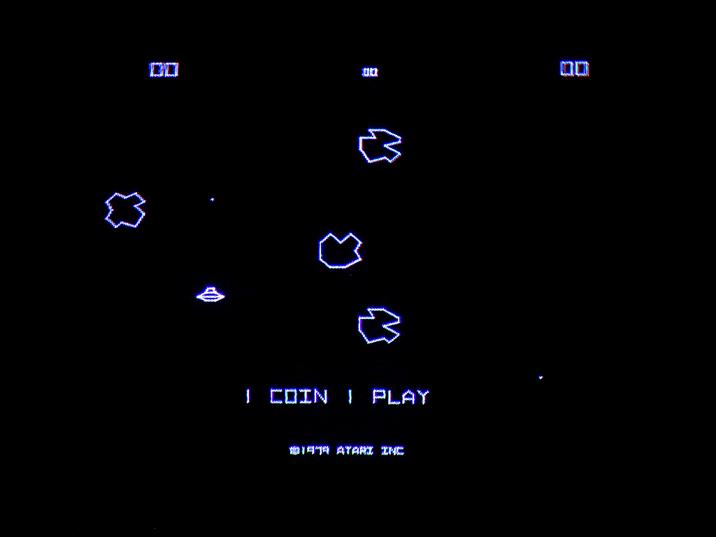
At The Airlock, there is a dead game in the corner called Hyperdrive.  In fact, it’s not just one but two dead games.  It appears that one side of it was dropped on it’s face.  The previous owner probably left it sitting somewhere without the seat portion attached.  If someone bumped it, it wouldn’t take much to knock it over.

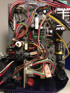
When it got knocked over, I believe the monitor was broken.  This theory comes from the fact that the monitors in each side are different.  Not only that, we have an extra monitor chassis board for the side that was not knocked over.  The monitor this game uses is the Sharp Image SI-727R-DS.  The 7 must be the series, 27 is the size, R is RCA tube and DS is dual scan if I’m not mistaken.

At first, the SI-727 seems like a beautiful chassis design.  It seems like it’s everything that any arcade operator could want in an arcade monitor.  It has fairly detailed silk screening on both sides of the PCB, switchable 15K/25K frequency, a nicely made remote board and it’s very easy to remove the chassis from the frame for servicing.

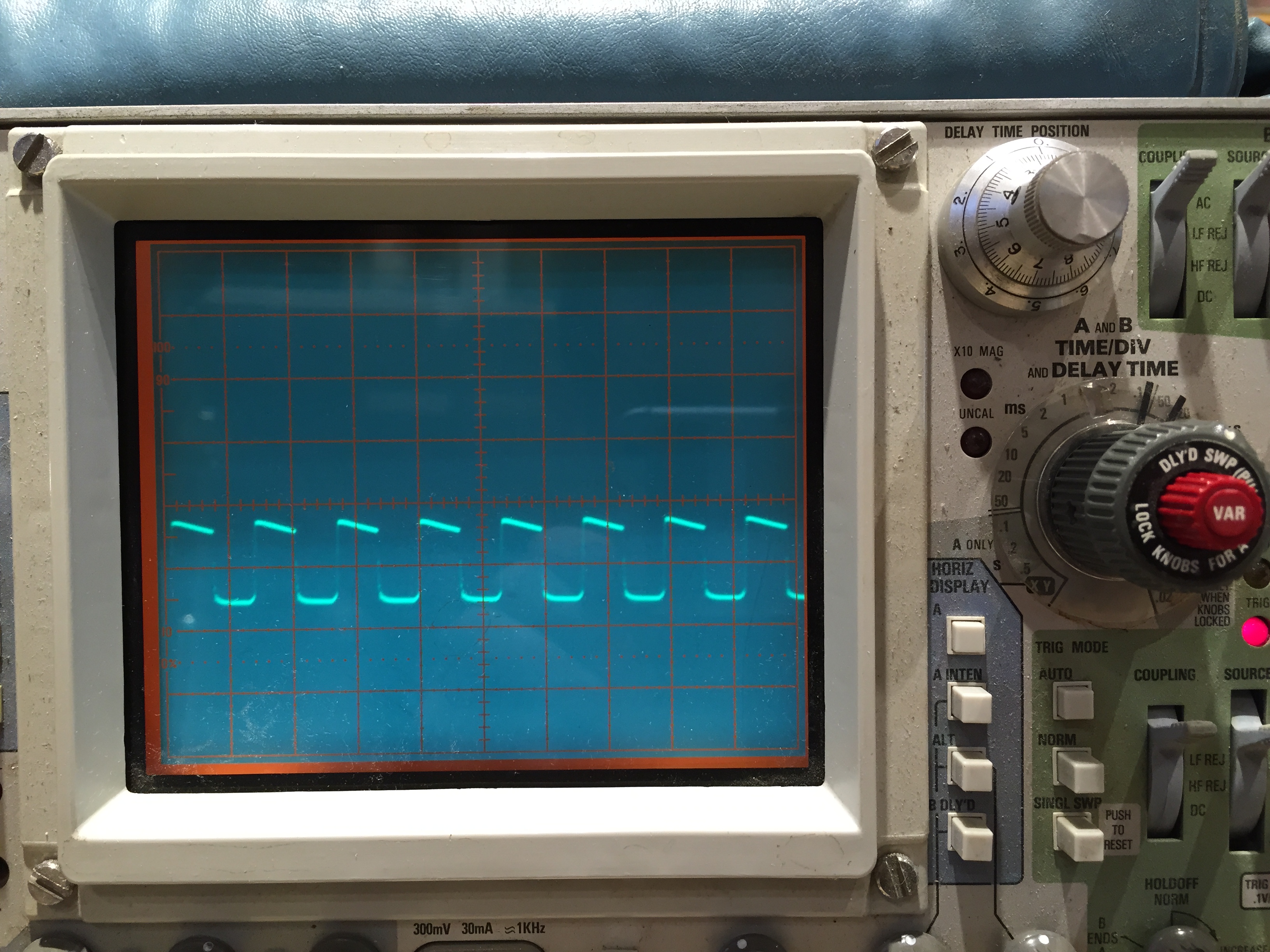
Further investigation reveals some problems however.   I have a SI-727R-DS board sitting here that I have nicknamed clicky.  We tend to nickname monitors with difficult or repeating problems at the airlock.  For instance, we have squishy, which is the radar screen in pod 4…. As you can guess, that one is vertically squished just slightly.  We recapped it, touched up the solder and it was still squished.  I think the problem may be a shorted diode in the vertical drive circuit but we haven’t had time to pull it back out to check.  We also have had other such as blinky, buzzy, etc.

The SI-727 is clicky though.  If I recall correctly, it makes a clicking noise when you fire it up.  This is most likely the power supply continually trying to power up and then power down when it realizes that the horizontal output transistor is shorted.  The question it, what has shorted the transistor?

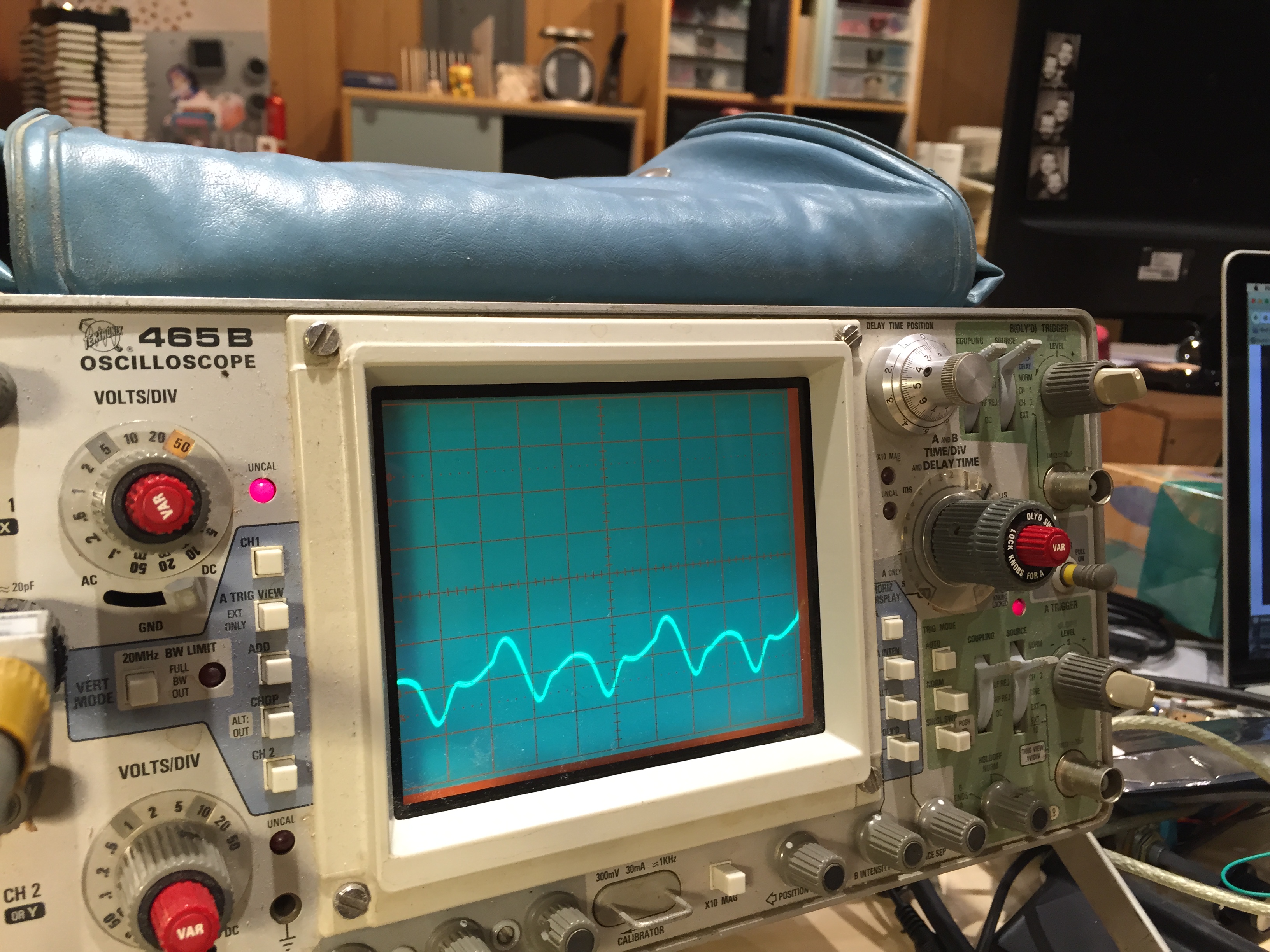
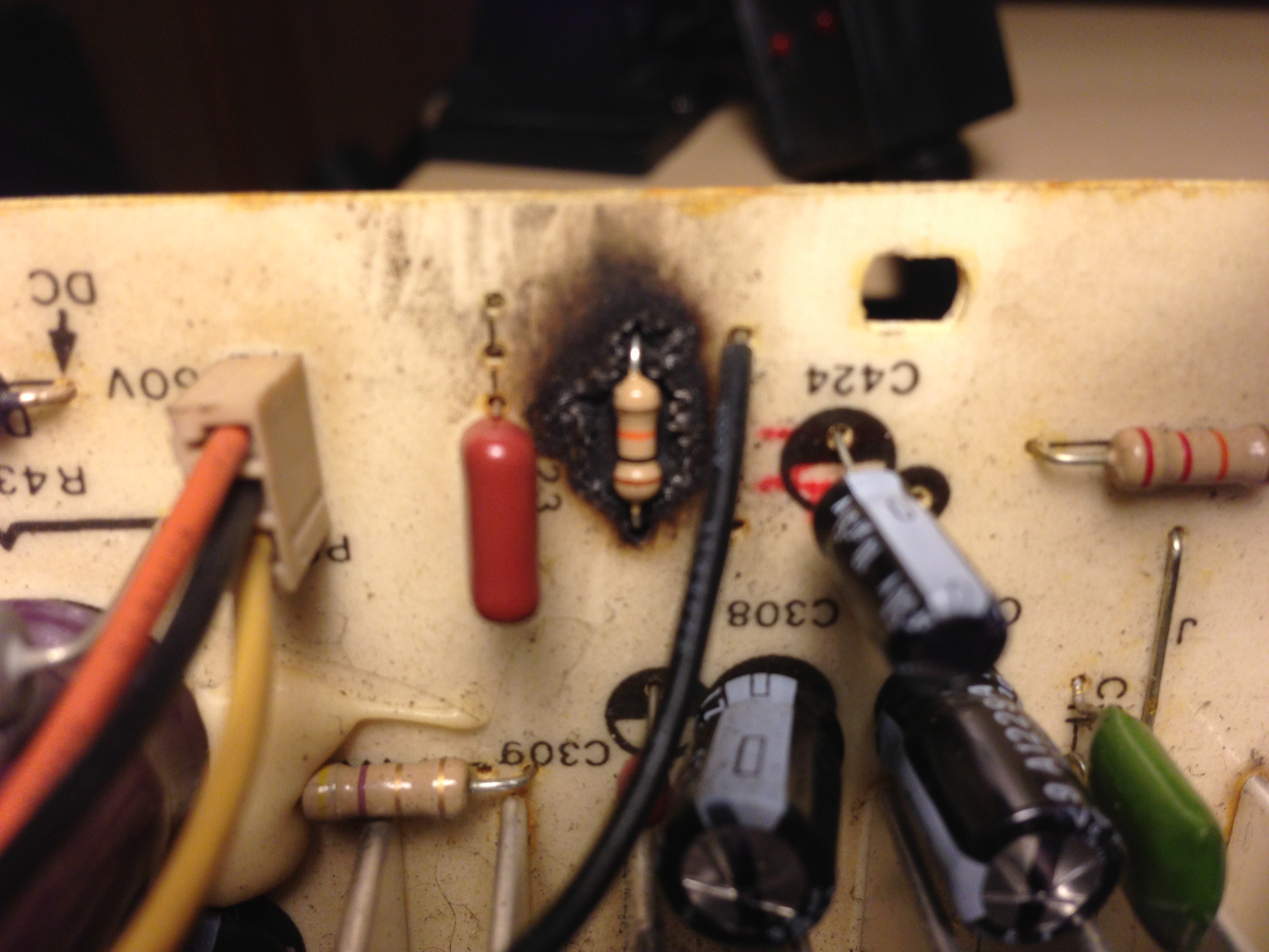
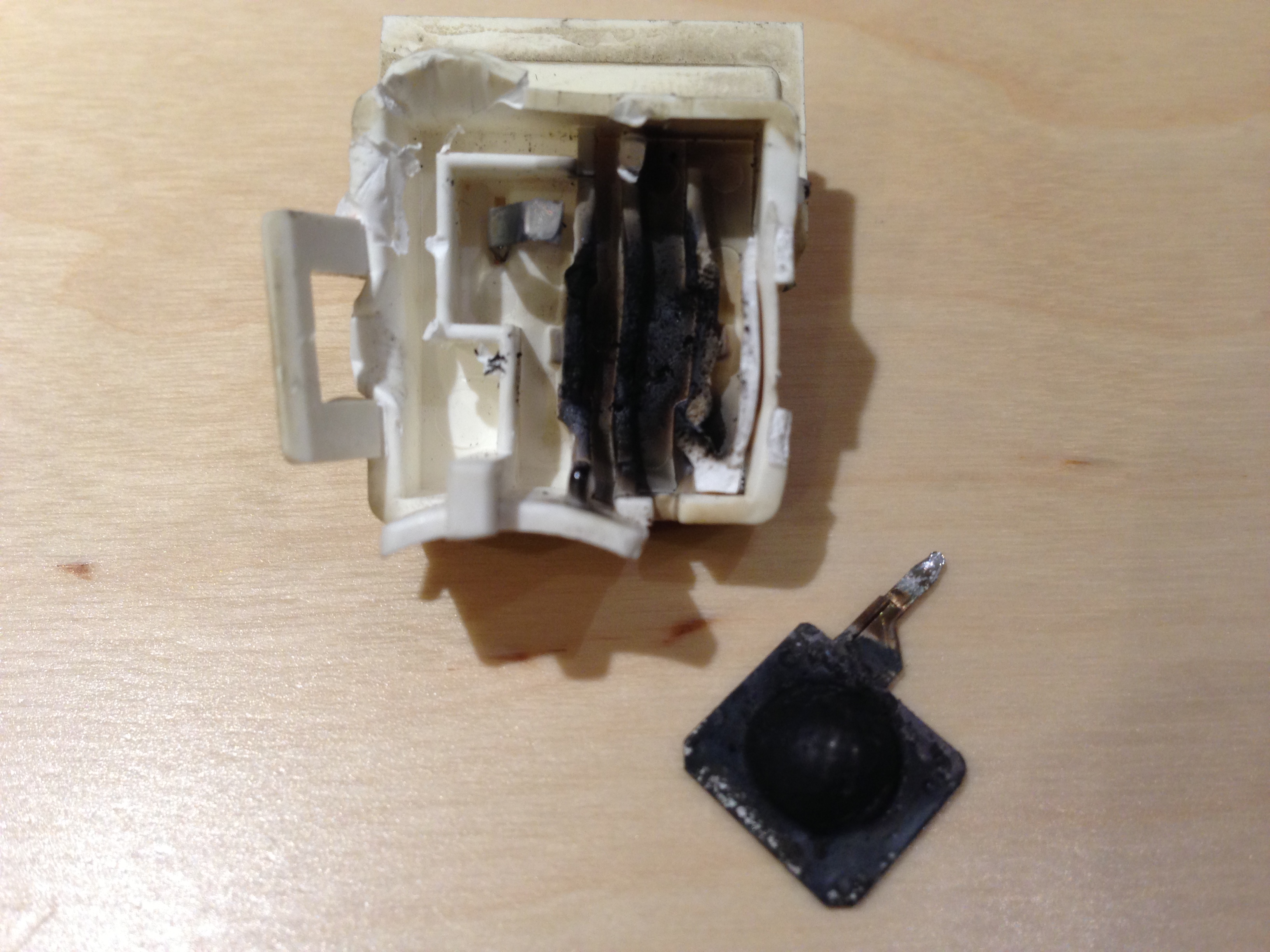
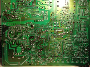
I’m really not sure yet.  This brings me to some of the problems I have experienced with the SI-727.  First off, it has some nasty trace rot.  The traces are far too happy to badly separate themselves from the PCB.  Usually this problem is indicative of using too high of a heat setting on your soldering iron but I recently upgraded my iron to an extremely bad ass Hakko FX-951.  The heat control on this iron is better than anything I’ve ever used or seen.  All that said, I think these PCB’s just weren’t made well in the first place.  In this picture, you can see the trace side of the board.  If you click on it, look very closely and you’ll see where I needed to lay some solder wick by the horizontal output transistor and use it to beef up the trace.  I’ve had to use this trick from time to time but usually it’s because a previous technician has screwed up the board.  in this case, just the act of removing the HOT tore up two of the pads.

IMG_0736

The other problem I have with this monitor is that I cannot find a service manual and/or schematic for it.  When a problem like this arises, it can be invaluable to refer to a schematic for troubleshooting.  Sharp Image, the company that made this monitor appears to be long since out of business but I used a sneaky trick to find their old site, The Wayback Machine!  Looking through this old site however proved to be a fruitless effort.  In ALL of the archived pages I checked, old and new, the SI-727 schematic was nowhere to be found.   Some forum post mentioned checking the SI-527 manual, which I did, but that was also a fruitless effort.  All of the components seem to have different reference numbers so that’s not going to be especially helpful.

I’m confident that we will get this issue sorted out but it might be tedious without the schematic…
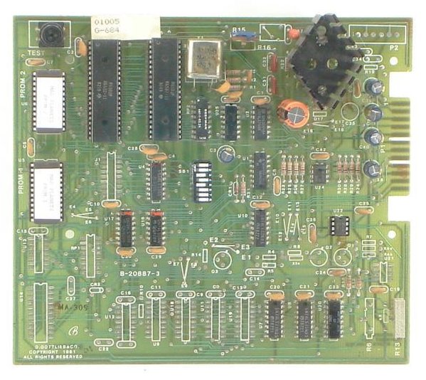
Asteroids Free Play part 1

asteroids

I knew it wouldn’t be long until another weird arcade issue surfaced.  This is one that has been troubling me since I worked on this machine.  The Airlock picked up a non-functioning Asteroids for fairly cheap a short while back.  Round one of fixing led James (with not much help from me) to bad ram chips.  Once he popped those in, the machine seemed to work until a week later when it didn’t.

During that entire week, the machine was left on freeplay as are most of the newest games when they first come into The Airlock while they are still in the functional testing phase.  The game died and so I took the board home and laid a mile of solder on it to fix all the questionable joints.  I also cleaned up and reseated a bunch of shaky looking roms in nasty wiper sockets.

When I popped the board back it, after a little bit of finagling, it fired right up… in German.  Not a problem, we tweaked up the dip switches and it was good to go.  We didn’t notice the latest problem until we tried to switch it off of freeplay mode.  Flipping the switch made the screen change to “1 coin, 1 play”.  Problem is that when you put in a coin, then play a game, after the game is over, both start lights are flashing as if there are credits on the machine.  Because there are.

We’ve had other bigger priorities to deal with so this was back burnered but I was out there tonight and by pure fluke, my dad called me.  I tend to pace around when I talk on the phone so I paced and walked by Asteroids and hit several of the buttons.  No one had played the game today because The Airlock was closed for a private party who was there only for Battletech.  After I hit the buttons, I noticed that the credit lights were now flashing.  Very curious.

I expect that the problem is that something is cross-wired in the coin door/control harness.  For instance, something may not be grounded properly or what someone thought was a ground is actually another control line and they have tied it together.  Kelly suspects that there is probably a short circuit on the logic board itself.  Maybe I got too carried away with fixing those solder joints?  Who knows.  When we figure it out, I’ll post our discoveries.

Powered by WordPress. Theme: Motion by 85ideas.