Category: electronics


Asteroids Free Play part 1

asteroids

I knew it wouldn’t be long until another weird arcade issue surfaced.  This is one that has been troubling me since I worked on this machine.  The Airlock picked up a non-functioning Asteroids for fairly cheap a short while back.  Round one of fixing led James (with not much help from me) to bad ram chips.  Once he popped those in, the machine seemed to work until a week later when it didn’t.

During that entire week, the machine was left on freeplay as are most of the newest games when they first come into The Airlock while they are still in the functional testing phase.  The game died and so I took the board home and laid a mile of solder on it to fix all the questionable joints.  I also cleaned up and reseated a bunch of shaky looking roms in nasty wiper sockets.

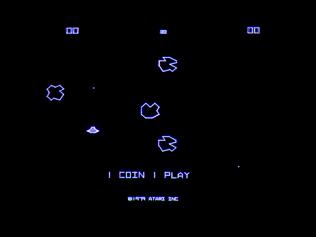
When I popped the board back it, after a little bit of finagling, it fired right up… in German.  Not a problem, we tweaked up the dip switches and it was good to go.  We didn’t notice the latest problem until we tried to switch it off of freeplay mode.  Flipping the switch made the screen change to “1 coin, 1 play”.  Problem is that when you put in a coin, then play a game, after the game is over, both start lights are flashing as if there are credits on the machine.  Because there are.

We’ve had other bigger priorities to deal with so this was back burnered but I was out there tonight and by pure fluke, my dad called me.  I tend to pace around when I talk on the phone so I paced and walked by Asteroids and hit several of the buttons.  No one had played the game today because The Airlock was closed for a private party who was there only for Battletech.  After I hit the buttons, I noticed that the credit lights were now flashing.  Very curious.

I expect that the problem is that something is cross-wired in the coin door/control harness.  For instance, something may not be grounded properly or what someone thought was a ground is actually another control line and they have tied it together.  Kelly suspects that there is probably a short circuit on the logic board itself.  Maybe I got too carried away with fixing those solder joints?  Who knows.  When we figure it out, I’ll post our discoveries.

Freeze Spray vs Donkey Kong

I’ve been spending a lot of my free time lately helping the guys over at The Airlock bring some of their newly acquired arcade games back up to good working order. The majority of the time, monitors are the problem area with these games.

One of the latest ones I fixed was Donkey Kong. It’s an original dedicated Nintendo cabinet from the early 80’s. One of the better looking design schemes out there. In the cabinet is the original Sanyo EZ 20 monitor mounted up on it’s side which is important to note for later…

This monitor had a weird problem. It lost all ability to hold the picture horizontally which appeared as vertical static since the monitor is mounted sideways. The weird thing though was that when you first turned it on, it was fine but then if you rebooted it, this condition existed. Sometimes it went into this condition after many hours of play though as well.p

With monitors, my usual starting point is caps. The electrolytic capacitors in this monitor appeared to be 30+ year old originals. CRT monitors are notoriously hard on caps. These games were only designed to last 2-3 years at the most since in the golden era of arcade, it was unfathomable that anyone would care about a game past that point.

Back to Donkey Kong though. Of course I started with the caps. I figured I had fixed it when I fired it back up to a perfectly clear picture. I turned it off to finish reassembling the monitor and when we turned it on to retest, we found our familiar squiggles.

Kelly, one of the guys at The Airlock, thought this may be a logic board problem in the video circuitry since it was a problem we were unfamiliar with in our experience of fixing monitors. After 20 feet of solder later and many questionable joints fixed on the logic board the problem still remained however.

Enter the freeze spray

Since the problem appeared only after the game warmed up, I figured that we may have a chance to pinpoint the faulty component with the old freeze trick. I grabbed a can of r134a that is on hand there and the little red straw and started blasting while someone watched the screen for me. It didn’t take long since the screen went back to a perfect picture practically on my first spray.

I power cycled the system and luckily the problem immediately reoccurred. We repeated this process, each time being more precise with the can of spray until we finally pinpointed the problem component, a 1/4w 1k resistor. Swapping that out fixed the problem and it’s been rock-solid ever since.

It was interesting to me that a resistor became heat sensitive. I was originally expecting it to be a solder joint, a cap(but they were all replaced) or a heat-sensitive IC perhaps.

After 6 months of talking about it, I finally gave my soldering 101 presentation at Black Lodge Research today.  If you were there or not, there are a few points that I was trying to drive home with this presentation.

  • Wash your hands and beware of lead
  • Clean your tip
  • Lead-free solder sucks ass!
  • Secure your work with fun tak

For those who missed it, sorry.  For everyone else, look forward to a couple of future classes on soldering surface mount devices and another one about making your own circuit boards at home.  Here are the slides and notes from the class:

Soldering 101 Open Office Presentation

Soldering 101 Presentation notes

Thanks to the folks who came out and made this talk fun and also thanks to the folks who dropped money in the donation box to help keep our hackerspace running.

Since I bought my Librettos for $15-$20/ea, I didn’t want to spend $40 on a rebuilt battery so I decided to have my friend James help rebuild a couple of the packs I have.

I have a 2 x 6-cell packs and 1 x 3-cell pack.  I purchased 9 “new” “Sony” 17670’s off of eBay.  I say new in quotes because they were not new when they arrived.  They obviously had been welded previously and someone ground the solder tabs off of them.  Also, we tested all 9 of the cells before we soldered up the pack.  Out of the 9, we found 3 of them at .66-1.30 volts.  When a Lithium Ion cell gets discharged to that point, you can kiss it goodbye.  It’s no longer viable because the chemistry changes and becomes less stable.  Another 3 were in the 2v ranges which may have been recoverable but probably not worth screwing with since it’s still outside of the specified operating range.  The final 3 were in the 3v range which was ok.  4.2v would be fully charged and none of them were anywhere near that.  Not that I’d expect them to be.

I say Sony in quotes because the batteries were counterfeit.  We could tell this because the physical structure of the cells are all slightly different and mismatched.  The blue jackets are printed at a very low quality level and are wrinkled in places where they’ve been improperly shrunk.

Counterfeit batteries are a HUGE problem on eBay.  I firmly believe that probably over 85% of the Lithium Ion batteries on eBay are counterfeit or of inferior/dangerous quality.  Most of them are extremely overrated as well.  For instance, a 18650 cell simply cannot hold 4000MaH.  It’s not physically possible for on of these cells output that much energy without draining it to an unusable state.

Whatever the case, our theory is that we are sending out batteries over to China to be recycled and they are disassembling the battery packs and reshrinkwrapping them and then selling them back to us on eBay.  Not sure if that’s the case with all of it but I’m sure that some of that is happening.

In the picture above, you can see very clearly the example of the wrinkled jackets.  Also, notice the real Sony cells on the right have different/darker colored jackets.

We finished the 3-cell battery up anyways with the 3 half-decent cells we picked from the batch.  I tossed it in my fancy outboard charger that came with one of the laptops and so far so good.  No heat and no smoke.  Time will tell if the rebuild was even worth the trouble.

I have been asked by a LOT of folks which soldering iron I recommend.  To give a little background, I used repair CRT monitors for a living back when A) a monitor was cheaper to repair than replace  B) crt monitors were still in style.  Sure it’s been a while but over the years I’ve used different irons.  At that particular job, I used a Weller solder station.  It wasn’t terrible but I can’t say it was overly impressive either.  It was cheap ($60) and it got the job done.  After that job, I didn’t buy my own solder station for years.  Instead I bought cheapo irons from Radio Shack like it was going out of style.  They used to be about $3 when I started buying them and now they are up to about $9.  These irons sort of got the job done over the years but they had problems.  I’ll just list off some of the top disadvantages that come to mind:

  1. They take forever to warm up to the proper temperature.
  2. They are unregulated so the temperature can be wildly inconsistent.
  3. The metals in the iron and tip are cheap and dissimilar.  After a while the tip will loosen and it will be impossible to properly tighten it.
  4. The plating on the tip seems to be prone to gumming up and eventually becomes impossible to clean.
  5. If you drop the iron on the cord, it will burn through the insulation.
  6. They don’t come with a stand and I consider the ones they sell unsafe.

The main advantage, price, won me over all those years but I’ve rounded up my “collection” of these irons and it amounted to a large pile.  I buy them like screwdrivers and strategically lose them in places where I’d likely remember to look later…

More recently, I’ve finally started soldering surface mount components on a regular basis so I decided I needed something that was regulated at the very least.  Enter the Hakko 936.  The 936 is NOT expensive for a solder station.  In fact, you can get it on Amazon for around $85-$95 typically.  Compared to my old Weller, it feels like a Mercedes Benz of soldering stations if there ever were such a thing.  Instead of my typical conversational review, I will just explicitly list the advantages here:

  1. Heats up in 10-15 seconds.
  2. Indicator light lets you know it’s on.
  3. Temperature is regulated and it bounces back fast when pressed.
  4. Comes with a beefy stand with an integrated sponge to keep the tip clean.
  5. Burn proof wire from the iron to the base unit.
  6. ESD safe. (seems to be, I haven’t fried anything with it)
  7. Light weight iron feels well balanced in your hand.
  8. Tip stays clean for a long time.
  9. Chisel tip included with the iron is very versatile.(for my uses at least)
  10. Don’t need a 15w, 25w and a 40w solder iron to do different jobs.  This one does it all.

There are probably even more advantages that I’m not thinking of but this list is a good start.  Back when I started buying the crappy Radio Shack irons, I didn’t really know any better and soldering stations were still $150-$200 for a professional grade model.  Thanks to global economics, demand and competition though, there are several choices under $150.  Yes, there is also the Aoyue 936 for $50.  I have not used it or compared them side-by-side but I can tell you that the Hakko looks, feels and performs like a professional piece of equipment.  It does what I expect, when I expect it and overall has exceeded my expectations.

By the way, the Hakko(at least mine) is made in Japan if you were wondering.  In the past, when I’ve tried to cut corners by purchasing the knockoff tool, I’ve ended up with something that doesn’t last and is disappointing.  Anyone who has ever shopped at Harbor Freight knows what I mean.  I expect the 936 will be the last soldering station I will ever need.  Now a hot air pencil is a different story 😉  Beyond the 936 models, there is also the digital readout version of the Hakko solder station but it’s considerably more expensive for something that won’t make your soldering a damned bit better.

I keep my soldering station pegged at 700 degrees.  If you are soldering something more sensitive or more heavy duty, adjust as needed obviously but 700 degrees seems to work well for my purposes.  If you have concerns about this, consult the data sheet of the component you are trying to solder.  Also, Don’t buy this awesome solder station and use crap solder.  Grab a spool of Kester 44 Rosin Core Solder 60/40.  I have a roll that I’ve been using since 2001(it’s dated) and it works great.  The lead free solder is complete and utter garbage in my experience.  It makes for lousy solder joints and is just generally hard to work with.

While you are rounding out your kit, a Flux pen and Chem-Wik desolding wick are both extremely nice to have.  Don’t buy 50′ of Chem-Wik from Amazon though.  They come in 5′ rolls that should be less than $5 or so.  Please feel free to comment on any experiences you’ve had with Hakko or Aoyue gear in the comments.  Happy soldering!

This project was started roughly 8 years ago when the large Boroughs B-7971 nixie tubes were still reasonably priced.  My friend scored these six tubes on eBay for $10/ea.  These particular tubes were salvaged from the ticker boards of the New York stock exchange. The clock uses an older Atmel AVR 90S2331 microcontroller as a CPU.  The code was written in bascom also by my friend after a two-year setback where my wife moved the clock while it was only half assembled and fried the first Atmel chip.  I originally modified my friend’s code in RVK but he decided to gut the code and rewrite it by the time we got around to revisiting this project.  I built the case out of 1/4″ oak that is obviously stained black.  There are no nails in it.  It was done entirely with wood glue and clamps since that’s what I had at the time I started the project.

My friend James painstakingly built the entire circuit on perf board for me.  The tubes are driven directly from 12 TD62084AP 8 channel high voltage driver ICs which are in turn driven by an array of 12 cascaded 74HC595N shift registers.  Other than that, there is a beefy power supply that puts out the 170v and some lower voltages for the logic circuitry.  It uses the 60Hz of the A/C line for a sync source.

I’m very pleased with how the final clock turned out.  It seems to keep the time very well.

GoodFET

I received my GoodFET PCB in the mail the other day and ordered up the parts from Digikey to build it out.  The parts(not including the PCB) were about $15.  My friend James actually built it for me on his hotplate since this was all surface mounted soldering and I didn’t feel like doing it with my iron.  That part went fairly easily and when I put it in the USB the lights flashed so everything seems to be working as far as I can tell.  When I brought it back home, I plugged it into my Gentoo system and worked through the next steps.

First off, I needed to install some prereqs:

emerge pyserial

emerge pysqlite

I also ended up having to add “sqlite” as a USE flag in the /etc/make.conf and then rebuilding python for that library to be available:

emerge python

Then I installed the firmware with:

./goodfet.bsl –fromweb

After that, I was able to perform the self test which took about a minute and a half:

./goodfet.monitor test

Everything went pretty smoothly as promised.  Next challenge is that I am going to attempt is to use the goodfet to unbrick a wrt54g.

At some point, some clever folks figured out that a NES controller contains a simple 8-bit shift register that can be read by a parallel port.  There are really just 3 things that matter.  Those are CLOCK, LATCH & DATA.  The rest of the pins and the diodes are just for power and ground.

With my version, I actually used one additional pin for power which was pin 4.  According to some sites, 1n914 diodes are ideal but in my case, I used 1n4001 diodes which were readily available at Radio Shack in a grab bag and they seem to work just fine.  I think that almost any silicon diodes will do the trick in this application.  The only reason for them is so the power is not back fed through the port as a side effect of tying all the lines together.  Overall, this is a GREAT beginner hack if you are just learning about electronics since it doesn’t even require a circuit board.

After the hardware was done, the software is the next piece of the puzzle.  I am using sneskey as my driver.  Sneskey is a slick little program that allows you to map many different types of controllers to keys on your keyboard.  You don’t really run sneskey in the background as a TSR though.  Instead, you set up the sneskey configuration file to load your emulator.  In my case, I used nesticle.  To set this whole thing up, download I would just extract all the sneskey files into the same directory as you extract nesticle and it’s companion program dos/4gw.  After that, you’ll want to edit the nes.ini file and change the ProgPath line to look something like this:

ProgPath = c:\nesticle\nesticle

Check the key bindings while you are in there.  They should be fine though.  After that, you should be able to launch nesticle and sneskey with the following command:

C:\nesticle>sneskey nes

Once you have launched the program with your controller plugged in, go to settings –>  input  –>  device 1.  In there, make sure Keyboard 1 is selected.  If all went well, everything should work except A & B.  Hit “redefine keys” and click on “A”, then press “A” on the gamepad to bind the key.  Repeat the process for “B” and you should now be good to go.

My final assembled XT-IDE 8-bit ISA card

Once I started messing with my IBM PC XT, I realized that there were things I had taken for granted all along since my first PC compatible system was a 386.  I didn’t realize that IDE uses a 16-bit bus and it would take some trickery to use an IDE device in an older 8-bit system like the XT.  I searched around and found that there were in fact 8-bit ISA controllers but they were expensive and rare.  Finding one these days would be a stroke of luck or a dent in the pocket book.  I was about to design my own when I came across the XT-IDE project.  The XT-IDE project is an open source venture where a group of people designed exactly what I needed with fairly common off-the-shelf parts.  I had my friend James to burn the code onto the eeprom for me  because I have no way to put something on a 360K floppy disc but aside from that, the project primarily consists of easy through-hole soldering.

Front side of the unpopulated XT-IDE PCB

I ordered my board the other day from Andrew Lynch who can be found lurking in this huge forum thread.  It was $14 including shipping which I felt was more than fair considering the quality of the board.  It’s a very professional dual-sided PCB with a full solder mask and silkscreen.  It would take me far too much time to attempt to replicate this at home.  It’s also nice that it has all of the settings printed VERY clearly on the board and the url for www.vintage-computer.com so I won’t forget where I found this project.

The bill of materials looks a little daunting at first but it’s really not a huge project.  The list below references Jameco part numbers.  There are a few non-critical items and some others that you can pillage from other ISA cards such as an L-bracket, pan screws and shorting blocks (jumpers).  I’m personally going to skip using most of the sockets since I’m fairly confident with my soldering skills and dual-wipe sockets tend to add another point of failure.

1               XT-IDE PCB (get this from Andrew lynch)
10   25523 	CAP,MONO,.1uF,50V,20%
1    1945428 	CAP,RADIAL,47uF,35V
2    45129 	IC,74HCT688
1    46316 	IC,74LS04
1    46607 	IC,74LS138
1    47466 	IC,74LS32
1    287144 	IC,74F245,DIP-20
3    282642 	IC,74F573,DIP-20
1    74827     	Atmel EEPROM IC, 28C64
2    112214 	SOCKET,IC,14PIN,DUAL WIPE
6    112248 	SOCKET,IC,DUAL WIPE,20PIN
1    112272 	SOCKET,IC,DUAL WIPE,28PIN
1    526205 	SOCKET,IC,16 PIN,390261-4
3    112432 	SOCKET,SHORTNG BLKS,RED,CLSE
1    690662 	RES,CF,150 OHM,1/4 WATT,5%
6    691104 	RES,CF,10K OHM,1/4 WATT,5%
2    857080 	MOLDED SIP,9PIN,BUSSED,10K,2%
1    333949 	LED,GREEN,572NM,T-1 3/4
1    1939562 	SWITCH,DIP,SPST,8-POS,16-PIN
1    53604 	HEADER,RT MALE,2RW,40 CONT
1    109568 	HEADER,.1 ST MALE,2RW,16PIN
1    109576     HEADER,.1 ST MALE,1RW,3PIN
2    2094389 	SCREW,PAN HEAD,PPN4-40X1/4
1    N/A        Keystone 9202 ISA bracket with 2 PCB mounting tabs.

Once I had all of the parts together, it was time to check out the build instructions.  This project is a VERY easy build.  All of the IC’s are labeled on the PCB, all of the caps are identical except one which is labeled and called out and all of the resistors are the same aside from the one that goes with the LED.  There are only two gotchas that I can think of.  First off, before you solder in the 40 pin IDE connector, you should pull the key pin out from the connector.  Grab an IDE cable and line it up with your connector, you will see which one is the key pin fairly quickly.  Secondly, the default dip switch setting is correct on the back side of the PCB but incorrect in the build instructions.  Set it to 01110111 as stated on the back of the card.  If you need to set this to a different setting, you will need to re-flash the firmware on the eeprom for some reason.  The default seems to work fine however so no big deal.

The original NCL MFM controller that came in my PC XT

Overall this project has cost me about $30.  I’ve learned some new stuff and I can now use my IBM PC XT with a modern IDE hard drive.  My next step will be to try to use the system with a compact flash card.  Now I can install MS-DOS 6.22 and hopefully Xenix at some point without disrupting the original MS-DOS 3.2 file system.

I have a small stack of WRT54G routers at my house.  When I find them second hand for cheap, they tend to be the WRT54G-TM variant.  This version is actually great for modding and hacking because people seem to think it’s tied to T-Mobile so it must require a contract to use or something and they will sell them cheap.  Personally I’ve had no trouble putting DD-WRT on the WRT54G-TM.  In fact, the WRT54G-TM has 32MB ram and 8MB which is far more than most of the other routers in the series.

Today, I’m going to add a serial port to my WRT54G-TM so I can use a terminal to log into it.  I think this will be handy for debugging since I plan to change the firmware on this router to Openwrt.  I’m going to use a debugging board given to me by an unnamed friend at an unnamed company.  There is nothing special about the board.  It’s just a serial level shifter with a Maxim 3221CAE IC on it.  It’s a fairly standard circuit that they publish on the datasheet for that IC.  I’m just using this board because it will save me time doing this hack.  The nice thing about the 3221 variant is that it will run on the 3.3V that is already present on the header.  I’m loosely following directions from here showing two serial ports added to a WRT54GS.

To mark out the location for my new serial port, I’m going to use fire.  I found a totally useless serial dock that corresponds with a defunct proprietary service and grabbed my blowtorch.  I heated up the end of the cable as hot as I could get it and made an impression inside the WRT54G-TM.  After that, I took a Dremel and routed out a hole for the DB9.

Next I soldered the wires in place.  On the Maxim chip, the r-out goes to the RXD pin on the header and the t-in on the chip goes to the TXD on the header.  3.3V on the header goes to VCC on the chip and GND goes to GND.  Make sure to leave the wires long enough to get the case closed again.  After I was satisfied with the soldering, I globbed on a LOT of hot glue to hold that little serial board in place.  Ignore my sd card mod since it’s not related to this hack.

Once it was all back together I fired up Minicom with the settings 115,200, 8, 1, no parity and no flow control.  The no flow control part is especially important.  Now when I boot up the router, I can see all of the debugging information.  Now with this serial port I can experiment with vlans and other things that can break your SSH session.  If I wanted to get really tricky, I could probably even use my hacked WRT54G-TM as a wireless-serial bridge for consoling into my Cisco routers that I keep in the garage.  They are too loud to keep by my desk.

If you like this article, you can support my site by using this link to buy your next WRT54G from Amazon.  You might also consider buying Linksys WRT54G Ultimate Hacking for more advanced hardware and software hacks for your WRT54G.

Powered by WordPress. Theme: Motion by 85ideas.